A discussion of the benefits of variable frequency drives often leads to a question regarding electrical harmonic distortion problems. When evaluating variable frequency drives, it is important to understand how harmonics are provided and the circumstances under which harmonics are harmful.
Harmonic Definition
In China, three-phase AC power typically operates at 50 hertz (50 cycles in one second). This is called the fundamental frequency.
A harmonic is any current form at an integral multiple of the fundamental frequency. For example, for 50-hertz power supplies, harmonics would be at 100 hertz (2 x fundamental), 150 hertz, 200 hertz, 250 hertz, etc.
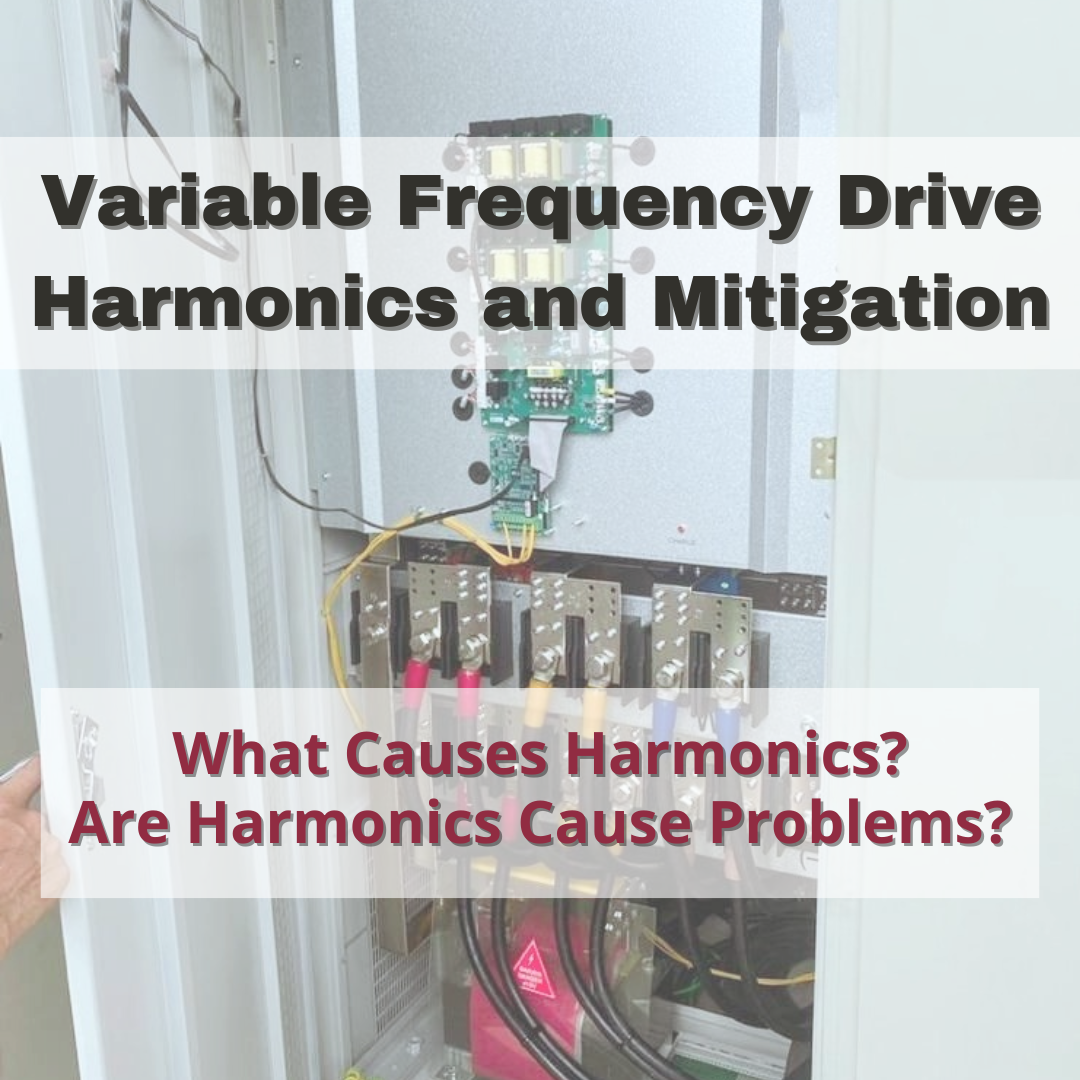
What Causes Harmonics?
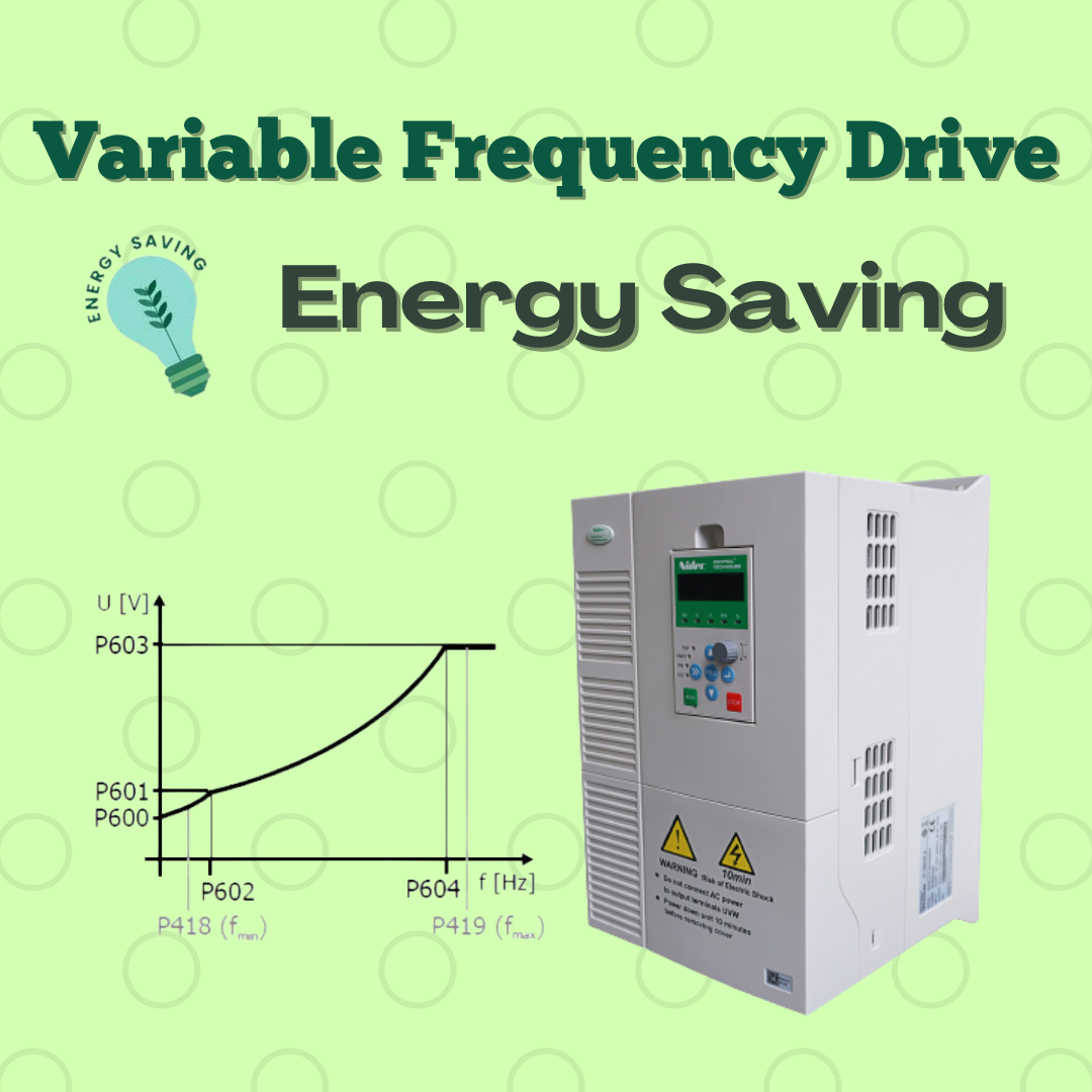
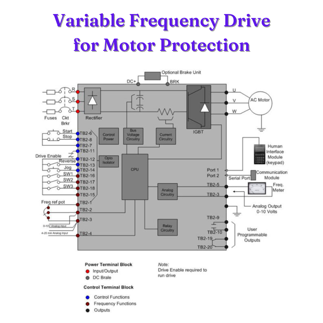
Variable frequency drives draw current from the line only when the line voltage is greater than the DC Bus voltage inside the VFD. This occurs only near the peaks of the sine wave. As a result, all of the current is drawn in short intervals (i.e., at higher frequencies). Variation in variable frequency drive design affects the harmonics produced. For example, variable frequency drives equipped with DC link inductors produce different levels of harmonics than similar variable frequency drives without DC link inductors. The variable frequency drive with active front end utilizing transistors in the rectifier section have much lower harmonic levels than variable frequency drives using diodes or silicon controlled rectifiers (SCRs).
Electronic lighting ballasts, uninterruptible power supplies, computers, office equipment, ozone generators, and other high intensity lighting are also sources of harmonic problems.
Rocks and Ponds
Obviously, the magnitude of the contributing wave forms has an effect on the shape of the resultant wave form. If the fundamental wave form (50 Hz) has a very large magnitude (5,000 amps) and the harmonic wave forms are very low (10 amps), then the resultant wave form will not be very distorted and total harmonic distortion will be low. If the harmonic wave form current value is high relative to the fundamental, the effect will be more dramatic.
In nature, we see this effect with waves in water. If you continually throw baseball size rocks into the ocean, you would not expect to change the shape of the waves crashing onto the beach. However, if you threw those same size rocks into a bathtub, you would definitely observe the effects. It is similar with electrical waves and harmonic distortion.
When you calculate harmonics you are calculating the effect of the harmonics on the fundamental current wave form in a particular distribution system. There are several programs that can perform estimated calculations. All of them take into account the amount of linear loads (loads drawing power through out the entire sine wave) relative to non-linear loads (loads drawing power during only a fraction of the sine wave). The higher the ratio of linear loads to non-linear loads, the less effect the non-linear loads will have on the current wave form.
Are Harmonics Cause Problems?
Harmonics that are multiples of 2 are not harmful because they cancel out. The same is true for 3rd order harmonics (3rd, 6th, 9th etc.). Because the power supply is 3 phase, the third order harmonics cancel each other out in each phase. This leaves only the 5th, 7th, 11th, 13th etc. to discuss. The magnitude of the harmonics produced by a variable frequency drive is greatest for the lower order harmonics (5th, 7th and 11th) and drops quickly as you move into the higher order harmonics (13th and greater).
Harmonics can cause some problems in electrical systems. Higher order harmonics can interfere with sensitive electronics and communications systems, while lower order harmonics can cause overheating of motors, transformers, and conductors. The opportunity for harmonics to be harmful, however, is dependent upon the electrical system in which they are present and whether or not any harmonic sensitive equipment is located on that same electrical system.
Understanding IEEE 519
IEEE (Institute of Electrical and Electronics Engineers) created a recommendation for calculating harmonics. The IEEE-519 standard provides recommended limits for harmonic distortion measured at the point of common coupling. The point of common coupling is the point at which the customer’s electrical system is connected to the utility.
Although the IEEE standard recommends limits for both voltage distortion and current distortion, specifications that reference a 5% harmonic limitation are generally referring to current distortion. In most cases, if the current distortion falls within IEEE-519 requirements, the voltage distortion will also be acceptable.
Determining compliance with IEEE-519 requires an actual measurement of the system during operation. Predicting compliance in advance often requires a system study that accounts for all electrical equipment (transformers, wires, motors, variable frequency drives, etc.) in the system.
Harmonic Terms
Total Harmonic Voltage Distortion – THD (V)
As harmonic currents flow through devices with reactance or resistance, a voltage drop is developed. These harmonic voltages cause voltage distortion of the fundamental voltage wave form. The total magnitude of the voltage distortion is the THD (V). The IEEE-519 standard recommends less than 5% THD (V) at the point of common coupling for general systems 69 kV and under.
Total Harmonic Current Distortion – THD (I)
This value (sometimes written as THID) represents the total harmonic current distortion of the wave form at the particular moment when the measurement is taken. It is the ratio of the harmonic current to the fundamental (non-harmonic) current measured for that load point. Note that the denominator used in this ratio changes with load.
 owner
owner 


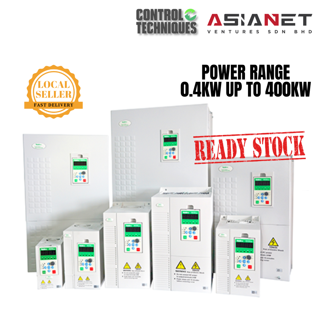

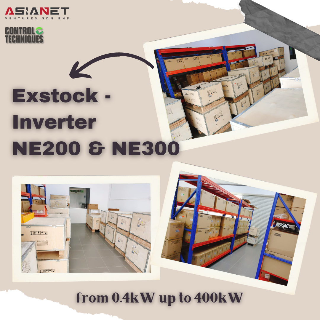
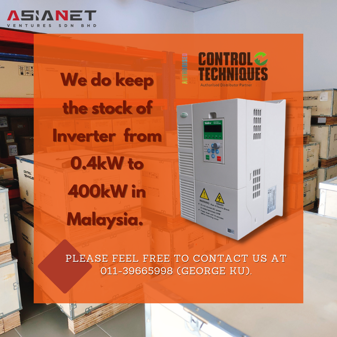
 Having a hard time sourcing for existing stock inverters, with reliable quality, good cost-effective, and well-established brand name in Malaysia?
 OUTSTANDING PERFORMANCE