电机马达使用变频器的好处

电机马达使用变频器的好处

变频调速能够应用在大部分的电机拖动场合,由于它能提供精确的速度控制,因此可以方便地控制机械传动的上升、下降和变速运行。变频应用可以大大地提高工艺的高效性(变速不依赖于机械部分),同时可以比原来的定速运行电机更加节能。下面例举使用变频调速的理由,来说明变频器应用日趋普及的基本认识:

1. 控制电机的启动电流

当电机通过工频直接启动时,它将会产生7至8倍的电机额定电流,这个电流值将大大增加电机绕组的电应力并产生热量,从而降低电机的寿命。而变频调速则可以在零速零电压启动(也可适当加转矩提升)。一旦频率和电压的关系建立,变频器就可以按照V/F或矢量控制方式带动负载进行工作。使用变频调速能充分降低启动电流,提高绕组承受力,用户最直接的好处就是电机的维护成本将进一步降低、电机的寿命则相应增加。

2. 降低电力线路电压波动

在电机工频启动时,电流剧增的同时,电压也会大幅度波动,电压下降的幅度将取决于启动电机的功率大小和配电网的容量。电压下降将会导致同一供电网络中的电压敏感设备故障跳闸或工作异常,如PC机、传感器、接近开关和接触器等均会动作出错。而采用变频调速后,由于能在零频零压时逐步启动,则能最大程度上消除电压下降。

3. 启动时需要的功率更低

电机功率与电流和电压的乘积成正比,那么通过工频直接启动的电机消耗的功率将大大高于变频启动所需要的功率。在一些工况下其配电系统已经达到了最高极限,其直接工频启动电机所产生的电涌就会对同网上的其他用户产生严重的影响。如果采用变频器进行电机起停, 就不会产生类似的问题。

4. 可控的加速功能

变频调速能在零速启动并按照用户的需要进行均匀地加速,而且其加速曲线也可以选择(直线加速、S形加速或者自动加速)。而通过工频启动时对电机或相连的机械部分轴或齿轮都会产生剧烈的振动。这种振动将进一步加剧机械磨损和损耗,降低机械部件和电机的寿命。另外,变频启动还能应用在类似灌装线上,以防止瓶子倒翻或损坏。

5. 可调的运行速度

运用变频调速能优化工艺过程,并能根据工艺过程迅速改变,还能通过远控PLC或其他控制器来实现速度变化。


6. 可调的转矩极限

通过变频调速后,能够设置相应的转矩极限来保护机械不致损坏,从而保证工艺过程的连续性和产品的可靠性。目前的变频技术使得不仅转矩极限可调,甚至转矩的控制精度都能达到3%~5%左右。


来源: <https://zhuanlan.zhihu.com/p/49752221>

变频器怎样维护保养?维护保养主要内容介绍

变频器怎样维护保养?维护保养主要内容介绍

随着工厂自动化技术的发展,变频器日益成为重要的驱动和控制设备,因此保障变频器可靠运行也成为设备保养、降低故障停机时间的重要议题。要确保变频器可靠连续地运行,关键在于日常维护保养。

1)日常。每天进行一次检查,记录运行中的变频器输出三相电压,并注意比较它们之间的平衡度;检查记录变频器的三相输出电流,并注意比较它们之间的平衡度;检查记录环境温度、散热器温度;察看变频器有无异常振动、声响,风扇是否运转正常。

2)定期。利用每年一次的大修时间,将重点放在变频器日常运行时无法检查的部位。

●除尘。对变频器进行除尘,重点是整流柜、逆变柜和控制柜,必要时可将整流模块、逆变模块和控制柜内的电路板拆出后进行除尘。将变频器控制板、主板拆下,用毛刷、吸尘器清扫变频器电路板及IGBT模块、输入输出电抗器等部位。电路板脏污的地方,应用棉布沾上酒精或中性化学剂擦除:

清扫空气过滤器冷却风道及内部灰尘,检查变频器下进风口、上出风口是否积尘或因积尘过多而堵塞。变频器因本身散热要求通风量大,故运行一定时间以后,表面积尘十分严重,需定期清洁除尘。对电路板、母排等除尘后,进行必要的防腐处理,涂刷绝缘漆,对已出现局部放电、拉弧的母排需去除其毛刺后,再进行处理。对已绝缘击穿的绝缘板,需去除其损坏部分,在其损坏部分附近用相应绝缘等级的绝缘板对其进行隔绝处理,紧固并测试绝缘合格后方可投入使用。

●检查交、直流母排有无变形、腐蚀、氧化,母排连接处螺钉有无松脱,各安装固定点处螺钉有无松脱,固定用绝缘片或绝缘柱有无老化开裂或变形,如有应及时更换,重新紧固,对已发生变形的母排需校正后重新安装。

●检查整流柜、逆变柜内风扇运行及转动是否正常,停机时,用手转动,观察轴承有无卡死或杂音,必要时更换轴承或维修。

●对输入、整流及逆变、直流输入快速熔断器进行全面检查,发现烧毁和老化的要及时更换。

●中间直流回路中的电容器有无漏液,外壳有无膨胀、鼓泡或变形,安全阀是否破裂,有条件的可对电容容量、漏电流、耐压等进行测试,对不符合要求的电容器进行更换,对新电容器或长期闲置未使用的电容器,更换前须对其进行钝化处理。滤波电容器的使用周期一般为5年,对使用时间在5年以上,电容容量、漏电流、耐压等指标明显偏离检测标准的,应酌情部分或全部更换。

●对整流、逆变部分的二极管、IGBT用万用表进行电气检测,测定其正向、反向电阻值,并在事先制定好的表格内认真做好记录,看各极间阻值是否正常,同一型号的器件一致性是否良好,必要时进行更换。

●对进线的主接触器及其他辅助接触器进行检查,仔细观察各接触器动静触头有无拉弧、毛刺或表面氧化、凹凸不平,发现此类问题应对其相应的动静触头进行更换,确保其接触安全可靠。

●仔细检查端子排有无老化、松脱,是否存在短路隐性故障,各连接线连接是否牢固,绝缘层有无破损,各电路板接插头接插是否牢固。进出主电源线连接是否可靠,连接处有无发热氧化等现象,接地是否良好。

3)变频器长时间不使用要做的维护有:电解电容器不通电时间不要超过3~6个月,因此要求间隔一段时间通一次电,新买来的变频器如离出厂时间超过半年至一年,也要先通低电压空载,经过几小时,让电容器恢复充放电性能后再使用。

在变频器的日常维护中也要按照规程去做,若发现变频器故障跳停时,不要就立即打开变频器进行维修,因为即使变频器不处于运行状态,甚至电源已经切断,由于其中有电容器,变频器的电源输入线、直流端子和电动机端子上仍然可能带有电压。断开开关后,必须等待几分钟后,使变频器内部电容器放电完毕,才能开始工作。当发现变频器跳停,就立即用绝缘电阻表对变频器拖动的电动机进行绝缘测试,从而判断电动机是否故障的方法是很危险的,易使变频器被烧。因此,在电动机与变频器之间的电缆未断开前,绝对不能对电动机进行绝缘测试,也不能对已连接到变频器的电缆进行绝缘测试。


来源: <https://www.sohu.com/a/365055077_723036>

变频器 (VFD) 与软启动器 (Soft Starter) 的区别和联系

变频器 (VFD) 与软启动器 (Soft Starter) 的区别和联系

变频器和软启动器其实是俩种完全不同用途的产品。变频器主要用在电机调速的地方,变频器拥有软启动器以及其他启动器的性能的同时,在启动特性上较其他的启动器装置也有很大的优势。在目前的启动控制领域,软启动器还占有很大的优势,那么相比之下,变频器的优势有哪些呢?

①启动转矩大,功率因数高。因为电动机的功率因数与工作频率有关,在电动机低速运行时工频电源下的功率因数远低于低频电源下的功率因数。变频器可以控制电动机从低频起步,且在整个启动过程中在接近额定电流的条件下始终保持比较高的功率因数和接近额定转矩的输出转矩。

②轻载或空载条件下,或启动期间采取减载卸载等措施时,变频器容量可以比电动机容量小。当然,启动完成后变频器需要退出运行。

③启动电流小。变频器-电动机拖动系统允许的启动时间可以很长。因为在这期间,电动机电流可以不超过电动机额定电流,因此,不论是变频器、电动机还是其他元器件均没有超常发热。由于启动电流小,因此需要的配电容量也是所有启动方式中最小的。

④采用变频器控制的电动机具有良好的动态、静态性能。由于变频器本身就是用于电动机调速的装置,因此,控制电动机的转速是其基本功能,启动过程可以实现任意控制,理论上可以人为随意设置任何启动速度曲线,这是其他方式所不具备的优势。

⑤用变频器拖动多台电动机启动时,即使被拖动电动机的容量有较大差异,也不会影响其启动性能。

⑥启动完成后,对电动机而言,需要一个供电切换过程,由变频器供电切换到电网供电。在整个过程中会出现诸如变频器安全、电流冲击。转速变化等问题。简而言之,存在切换问题,所谓软切换就是安全、平稳的切换。


来源: <https://zhuanlan.zhihu.com/p/76421508>

什么是变频器,原理是什么,有什么作用?

什么是变频器,原理是什么,有什么作用?

什么是变频器这个东西, 总体上来就是:交流——直流——交流 (也可以说是先整流——再逆变) ,经过这种处理过程的变频器也叫交直交变频,目前也是各个行业用的比较多的一种。此外,还有一种交流——交流变换的,这种也被称为交交变频器。

一、什么是变频器

变频器是利用电力半导体器件的通断作用将工频电源变换为另一频率的电能控制装置。变频器主要由整流(交流变直流)、滤波、逆变(直流变交流)、制动单元、驱动单元、检测单元微处理单元等组成的。

变频器是把工频电源(50Hz或60Hz)变换成各种频率的交流电源,以实现电机的变速运行的设备,其中控制电路完成对主电路的控制,整流电路将交流电变换成直流电,直流中间电路对整流电路的输出进行平滑滤波,逆变电路将直流电再逆成交流电。对于如矢量控制变频器这种需要大量运算的变频器来说,有时还需要一个进行转矩计算的CPU以及一些相应的电路。变频调速是通过改变电机定子绕组供电的频率来达到调速的目的。

二、变频器的原理

在嵌入式开发中,经常会涉及到对电机的控制,目前交流电动机的变频控制应用非常广泛,所以我们来简单看图介绍下变频器,假设各位已经了解电机的原理。

变频器主要由整流(交流变直流)、滤波、逆变(直流变交流)、制动单元、驱动单元、检测单元微处理单元等组成。变频器靠内部IGBT的开断来调整输出电源的电压和频率,根据电机的实际需要来提供其所需要的电源电压,进而达到节能、调速的目的,另外,变频器还有很多的保护功能,如过流、过压、过载保护等等。随着工业自动化程度的不断提高,变频器也得到了非常广泛的应用。

典型的变频器系统图如下所示. 主要包括,操作面板,VFD控制器,电机等部分

主要包括:控制平台,测量电路,功率电路,保护电路等

常见的变频器有两种类型:电压型和电流型,其中功率逆变部分多使用IGBT和IGCT等功率管。

三、变频器的作用

1、变频节能

变频器节能主要表现在风机、水泵的应用上。为了保证生产的可靠性,各种生产机械在设计配用动力驱动时,都留有一定的富余量。当电机不能在满负荷下运行时,除达到动力驱动要求外,多余的力矩增加了有功功率的消耗,造成电能的浪费。风机、泵类等设备传统的调速方法是通过调节入口或出口的挡板、阀门开度来调节给风量和给水量,其输入功率大,且大量的能源消耗在挡板、阀门的截流过程中。当使用变频调速时,如果流量要求减小,通过降低泵或风机的转速即可满足要求。

电动机使用变频器的作用就是为了调速,并降低启动电流。为了产生可变的电压和频率,该设备首先要把电源的交流电变换为直流电(DC),这个过程叫整流。把直流电(DC)变换为交流电(AC)的装置,其科学术语为“inverter”(逆变器)。一般逆变器是把直流电源逆变为一定的固定频率和一定电压的逆变电源。对于逆变为频率可调、电压可调的逆变器我们称为变频器。变频器输出的波形是模拟正弦波,主要是用在三相异步电动机调速用,又叫变频调速器。对于主要用在仪器仪表的检测设备中的波形要求较高的可变频率逆变器,要对波形进行整理,可以输出标准的正弦波,叫变频电源。一般变频电源是变频器价格的15-20倍。由于变频器设备中产生变化的电压或频率的主要装置叫“inverter”,故该产品本身就被命名为“inverter”,即:变频器。

变频不是到处可以省电,有不少场合用变频并不一定能省电。 作为电子电路,变频器本身也要耗电(约额定功率的3-5%)。一台1.5匹的空调自身耗电算下来也有20-30W,相当于一盏长明灯. 变频器在工频下运行,具有节电功能,是事实。但是他的前提条件是:

第一、大功率并且为风机/泵类负载;

第二、装置本身具有节电功能(软件支持);

变频器(Variable-frequency Drive,VFD)是应用变频技术与微电子技术,通过改变电机工作电源频率方式来控制交流电动机的电力控制设备。变频器主要由整流(交流变直流)、滤波、逆变(直流变交流)、制动单元、驱动单元、检测单元微处理单元等组成。变频器靠内部IGBT的开断来调整输出电源的电压和频率,根据电机的实际需要来提供其所需要的电源电压,进而达到节能、调速的目的,另外,变频器还有很多的保护功能,如过流、过压、过载保护等等。随着工业自动化程度的不断提高,变频器也得到了非常广泛的应用。


来源: <https://zhuanlan.zhihu.com/p/54285732>

尼得科CT高功能矢量驱动器NE200应用在真空泵永磁电机上,抗负载突变能力强,最高频率可达3300Hz

尼得科CT高功能矢量驱动器NE200应用在真空泵永磁电机上,抗负载突变能力强,最高频率可达3300Hz

尼得科CT高功能矢量驱动器NE200,抗负载突变能力强,最高频率可达3300Hz,功率范围0.37-900KW,可驱动同步异步电机,可开环、闭环矢量控制,在真空泵永磁电机高频的应用,能够完全满足客户多项需求。

一、案例背景介绍

真空泵按工作原理可分为两种类型,即气体传输泵和气体捕集泵,随着真空应用技术在生产和科学研究领域中对其应用压强范围的要求越来越宽,大多需要由集中真空泵组成真空抽气系统共同抽气后才能满足生产和科学研究过程的要求,因此选用不同类型真空泵组成的真空抽气机组进行抽气的情况较多。

传统技术的真空泵采用异步鼠笼式电机或直流电机,一般直流电机需要经常维护(更换碳刷、过滤网),异步电机或直流电机的效率均比较低;相比于异步电机和直流电机,永磁同步电机具有结构简单、运行可靠、体积小、质量轻、损耗小和效率高等诸多优点,永磁同步电机能够很好的满足真空泵市场需求,遍及电力、化工、制药和环保各个行业,本次应用即为永磁同步电机。

二、应用配置

设       备:真空泵设备(抽真空)

驱  动  器:NE200-2S0022GB (单相220V,2.2KW,10A。)

电       机:LS永磁同步电机,1.5KW,155V,额定电流8.3A,额定频率300Hz,9000转(4级电机),反向电动势14V/1000rpm。

工艺要求:300Hz定频运行,60秒轻载,5秒重载,24小时周期运行。轻载是真空泵进气口完全关闭,重载是真空泵进气口完全打开,通过气阀控制。加重载时要求变频器频率不跌落或者跌落后能快速回调(1~2秒内),对变频器动态响应要求高。

测试工况:分三种工况,先测试第一种工况,满足工艺要求后再测试第二,第三种工况。

第一种:电机只带真空泵,重载时相当于最大负载的80%。

第二种:电机带真空泵,真空泵排气口增加尾排管(会增加排气阻力),重载时相当于最大负载的90%。

第三种:电机带真空泵,真空泵进气口增加气灌(会增加进气阻力),排气口增加尾排管(会增加排气阻力),重载时相当于最大负载(设备实际现场应用工况)。

三、应用调试

1、恢复出厂设置:FP.02=2(恢复出厂值)

2、参数设置

F0.01=1         (SVC)

F0.10=300Hz (基本频率,同电机额定频率)

F0.11=350Hz (最大频率)

F0.12=350Hz (上限频率)

F0.14=155V   (最大输出电压)

F0.19=10s     (加速时间)

F5.00=2         (电机类型:选择永磁电机)

F5.01=4         (电机级数)

F5.03=8.3A   (额定电流)

F5.04=9000  (额定转速)

FP.05=0        (G型机)

3、电机自学习

F5.10=2(旋转自整定)

学习到以下电机参数

F5.11=454mΩ(定子电阻)

F5.12=2.68mH(Ld电感)

F5.13=3.10mH(Lq电感)

F5.14=8.9V     (反向电动势)

4、注意:

NE系列是最高频率对应的反向电动势电压,M系列是1000rpm对应的反向电动势电压。

Source: <https://www.sekorm.com/news/77177550.html>

How to Wire a VFD?

How to Wire a VFD?

CAUTION: WE HIGHLY RECOMMEND YOU HIRE A LICENSED ELECTRICIAN OR CERTIFIED TECHNICIAN TO WIRE YOUR VFD AND MOTOR.

STEP 1: Make sure everything is correctly sized and accounted for

  • Look at the nameplate on your motor and make sure your VFD is sized correctly.
  • How many full load amps does your motor draw?
  • Is your VFD rated for the amount of amps your motor draws?
  • How many volts does your motor require (460V or 230V)?

STEP 2: Make sure you have a properly-sized circuit breaker rated for your amps and VFD

  • Locate your breaker panel.
  • Remove the dead front and the panel cover.
  • Install your 3 pole amp rated, volt rated, circuit breaker.
  • If you can kill power to the breaker panel before you work inside it, we recommend you do so. If you are unable to do so, make sure you wear the proper safety equipment (leather gloves, safety glasses, arch fault gear, etc.).

STEP 3: Run Wires – (3) power wires and (1) ground wire from your breaker panel to your VFD

  • Make sure your power wire is rated for the Full Load Amps (14 gauge wire up to 15 amps, 12 gauge wire up to 20 amps, 10 gauge wire up to 30 amps, 8 gauge wire up to 40 amps, 6 gauge wire up to 50 amps, 4 gauge wire up to 70 amps, 2 gauge wire up to 100 amps, and so on).
  • If your power wires are #6 up to #2, your ground wire can be #10. For power wires larger than #2, see chart for proper ground wire sizing.
  • Use appropriate wiring method in determining your raceway for wires. Some possible options are: EMT Conduit, Rigid Conduit, Flexible metal conduit (Flex), Metal Clad Cable (MC), NMB Cable (Romex), etc.

STEP 4: Run wires from VFD to motor

  • Use the same gauge wires as you did from the circuit breaker to the VFD.
  • Use proper raceway as you see fit.
  • Land wires in conduit box on motor.

STEP 5: Make-up wires in your motor

  • Use the wiring diagram on your motor to determine the correct wiring method.
  • Most 3 phase motors are dual-voltage, meaning they will accept 480/460 volts or 240/208 VAC.
  • The way you make up the motor will be dependent upon the voltage. Be sure to make it up correctly depending on the amount of voltage you are providing.
  • Use wire nuts to tie your power wires to the proper wires as shown on the motor name plate.
  • Pull on wire nuts to make sure the wires are spliced correctly and are tight. If a wire slips out of the wire nut you know you have a problem and need to redo it.
  • Fasten conduit box cover to motor.

STEP 6: Terminate wires to your VFD

  • Terminate your load wires (wires going to the motor) to the terminals U, V, W.
  • Terminate your line wires (wires coming from the circuit breaker) to terminals R/L1, S/L2, T/L3.
  • If you’d like, you can use crimp terminals. You can also just put a small hook shape in your stripped wire and land it under the screws.
  • Land your ground wires under the green ground screw.

STEP 7: Terminate your wires to your circuit breaker in your panel

  • Land your 3 power wires to the circuit breaker.
  • Land your ground wire to the ground bus bar.
  • Put the dead front and panel cover back on.

STEP 8: Start up

  • Turn the circuit breaker on.
  • Program your VFD to your preferred parameters (See also “Programming Your VFD).
  • Use your preferred starting method (e.g., start/stop buttons, Keypad on VFD) to start the motor.
  • Enjoy the speed control that is now possible with your VFD.
 
 
Source: <https://vfds.com/blog/how-to-wire-a-vfd/>

Can a VFD Convert Single-Phase Power to Three-Phase?

Can a VFD Convert Single-Phase Power to Three-Phase?

Using VFDs To Convert Single-Phase To Three-Phase

Single-phase AC power is common in many residential and agricultural settings, although it can also be seen in some industrial locations. It typically will only have two phases (L1 & L2) and possibly a neutral. It is common to see single-phase power for 120, 240, and occasionally 480 VAC systems.  Three-phase supplies have three phases (L1, L2, & L3).  Three-phase power in the United States is typically 240 and 480 VAC systems. There are some instances where up to 600 VAC systems are used as well.

Many people run in to problems with phase conversion when they get a new or used motor and find that the three-phase motor doesn’t play well with their single-phase power.

Yes, a VFD can power a three-phase motor with a single-phase input power supply, but phase conversion introduces many considerations that normally don’t factor in to buying a VFD. In this article we will dig in to VFDs that are built to convert single-phase to three-phase, how to use a regular VFD when custom VFDs are not an option, and other options for phase conversion when VFDs are not the best choice.

Single-Phase Input VFDs

Many manufacturers have lines of VFDs built to input single-phase power and output three-phase power. 

In fact, the VFDs that are designed this way aren’t able to input three-phase power at all. This is because the AC power input only has two available terminals for the hot wires and therefore can’t take the additional wire required for three-phase input.

If what you need is a VFD that is ready off the shelf to convert single-phase to three-phase, this is often a great option for you. These VFDs are rated and sized based on the output three-phase current rating of your motor, making them simple to size correctly and easier to install.

One drawback to VFDs that are set up this way is that they typically only run smaller motors. Another problem is if the site ever updates to three-phase power. Although the cost of switching the entire system to three-phase power makes it unlikely to happen very often, if it does happen then these VFDs are not able to function on a three-phase system. These VFDs tend to be cheaper than most, but it still is a shame to throw them out if they become obsolete.

Using Standard VFDs for Phase Conversion

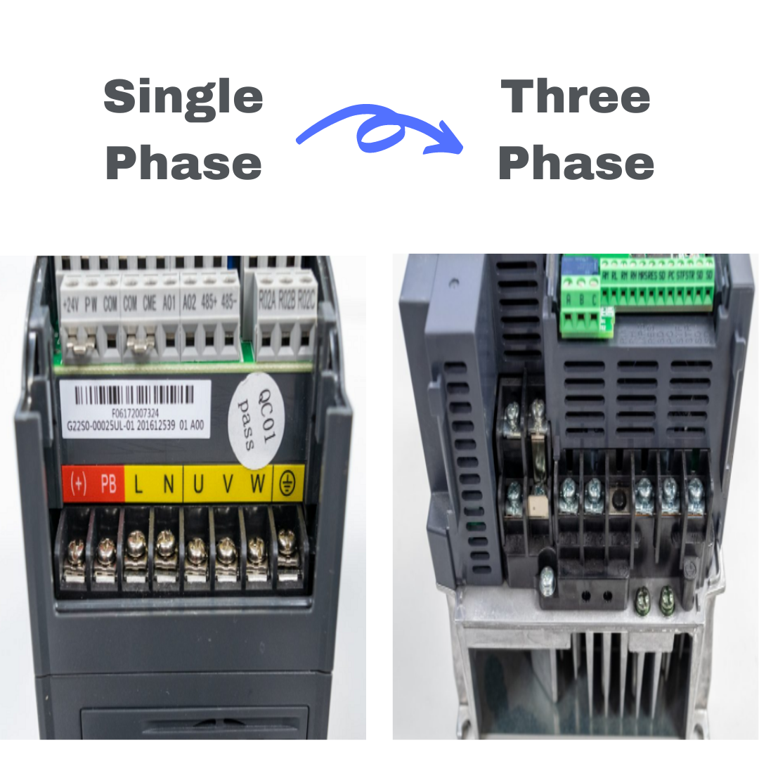
If your motor is too large for VFDs built for phase conversion, it is possible to use a standard VFD for your single-phase power supply. This is done by putting the two hot wires for single phase on the AC input for the VFD and leaving one input terminal open and unused. This does raise a few problems that you have to factor in.

Because you are now concentrating the same amperage on two phases instead of three, failure of your VFD’s input diodes is likely to happen. To resolve this issue, you have to oversize the VFD to account for larger ampacities. A conservative rule of thumb is to double the size of the VFD you need.

For example, if your motor Full Load Amps (FLA) is listed at 15, double that and size a VFD as if you needed to power a 30-amp motor. 

This process of de-rating a standard VFD does have some drawbacks. Compared to powering a three-phase motor with a three-phase input, you are buying a much bigger drive, which means more money and space. We always recommend to try and use a three-phase power source to power your motors if possible, but sometimes that is not an option.

Another issue to consider is how this use affects warranty. There are many VFD brands, and whichever one you choose will likely have its own warranty policies. If using a VFD this way voids your warranty, you may want to consider other options.

Other Phase Conversion Options

There are cases where VFDs are not the best option to convert phase. One of the most common problems we see with VFD phase conversion is that someone is trying to convert single-phase to three-phase for more than just a motor. While a VFD will do well at converting phase for an AC motor, it won’t work right at converting power for the peripheral devices you’re also trying to run, often including things like relays, lights, control power transformers, and other electronic devices.

If you are also not looking to control the speed of a motor, you will end up paying for a lot of functionality in a VFD that you won’t use. VFDs are primarily used to control the speed of a motor, so if you want a motor to run at full speed all the time, you might be over-engineering your system.

In cases like these, you should look at phase converters. There are several types, each with their positives and negatives. Static phase converters are a very budget-friendly option, but typically won’t run a motor at its full rating. Rotary phase converters do a great job of converting power, but have moving parts and create a lot of noise. Digital phase converters tend to perform best at getting the full rating out of a motor while converting phase, but are a more expensive option.

Source: <https://vfds.com/blog/can-a-vfd-convert-single-phase-power-to-three-phase/>