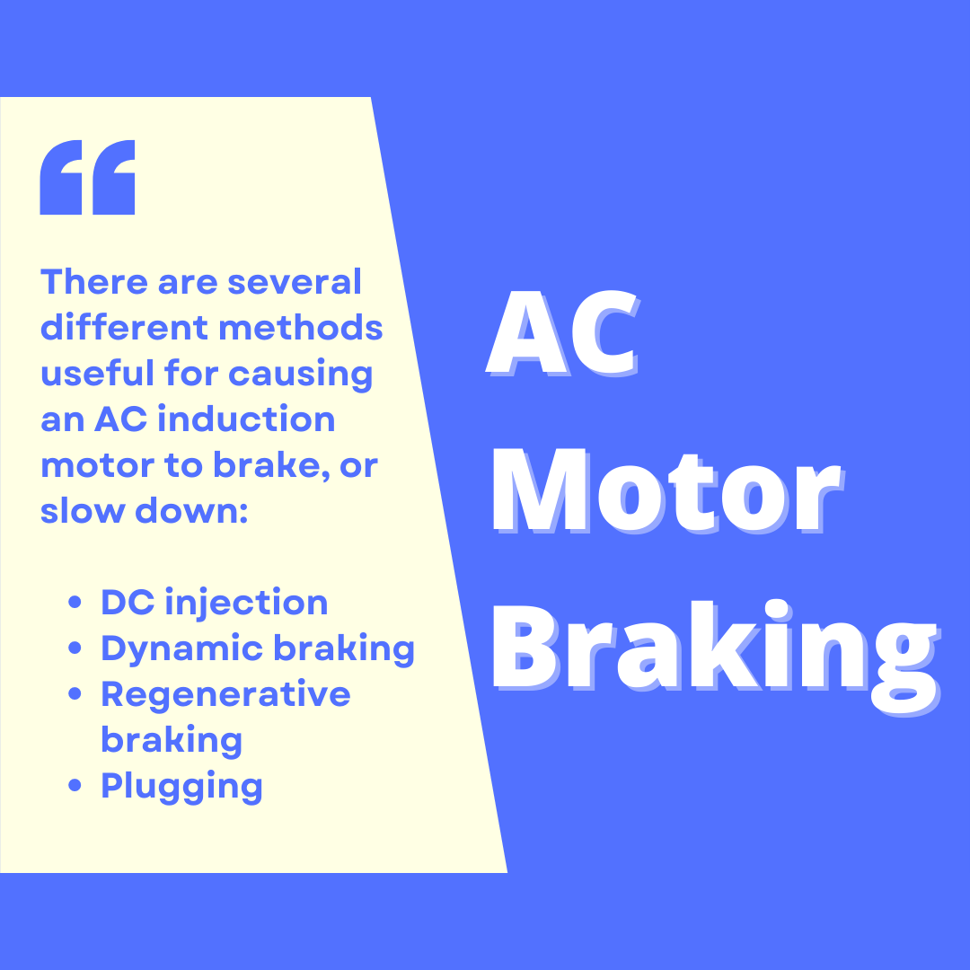
AC Motor Braking
There are several different methods useful for causing an AC induction motor to brake, or slow down:
- DC injection
- Dynamic braking
- Regenerative braking
- Plugging
DC injection uses the technique of energizing the stator windings with low-current DC instead of high-current AC as is the case when the motor runs. Dynamic braking works the motor as a generator, dissipating energy through a resistive load. Regenerative braking also works the motor as a generator, but instead of wasting energy in the form of resistive heating, a regenerating motor drive pumps that energy back into the power supply grid where it may be used by other loads. Lastly, plugging works by applying reverse power to the motor, and is the most aggressive means of bringing any motor to a halt.
All electronic motor braking techniques enjoy the advantage of mechanical simplicity. If the motor itself can be used as a brake, then a separate mechanical brake may not be needed. This simplifies the machinery of a system and potentially reduces maintenance costs.
A significant disadvantage of electronic braking techniques is that they all depend on the proper function of the motor drive, and in some cases the AC line power as well. If a VFD’s braking ability depends on the presence of AC line power, and that line power suddenly is lost, the VFD will have no braking capacity at all! This means a large motor might suddenly have no ability to brake in the event of a power outage or a tripped circuit breaker, which could be a serious safety issue in some applications. In such cases, one must ensure the presence of other (alternative) braking methods to function in the event of line power failure.
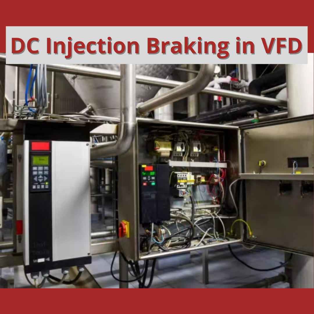
DC injection braking
If a spinning AC induction motor’s stator coils are energized with DC rather than AC, the rotor will find itself spinning inside a stationary magnetic field. This causes currents to be induced in the rotor bars, which in turn causes a braking force to develop in the rotor in accordance with Lenz’s Law. The effect is exactly opposite of what happens when a motor is energized from a stand-still: there, currents are induced in the rotor bars because the rotor is stationary and the stator field is rotating. This method of braking is quite effective, with only small amounts of direct current through the stator winding being necessary to cause a large braking torque.
The braking torque produced by DC injection varies directly with the magnitude of the DC injection current, and also directly with the speed of the rotor. This means the braking force created by DC injection tends to diminish as the motor slows down to a stop.
When any motor acts as a brake, the kinetic energy of the motor and the mechanism it attaches to must go somewhere. This is a basic tenet of physics, codified as the Law of Energy Conservation: energy cannot be created or destroyed, only altered in form. When DC injection is used to brake a motor, the braking energy is dissipated in the form of heat by means of the induced currents circulating through the rotor bars and shorting rings. This is something one must be careful to consider when choosing DC injection as a braking method: can the rotor safely dissipate the heat when needed? Repeated braking cycles, especially with little time between cycles, may overheat the rotor and cause damage to the motor.
Modern solid-state AC motor drives easily provide DC injection for braking. All they need to do is energize their output transistors in such a way that one or more of the stator windings sees a constant voltage polarity instead of an alternating polarity as is the case when the motor is running. The following diagram shows the power flow into the motor during DC injection:

The intensity of the DC injection current may be varied by altering the pulse-width duty cycle of the transistors used to switch the braking current.
Dynamic braking
If a powered AC induction motor spins at a speed faster than its rotating magnetic field, it acts as a generator: supplying power back to the voltage source, transferring kinetic energy from the spinning rotor and machinery back into electrical power. This makes for an interesting experiment: take an internal combustion engine, steam turbine, water turbine, or some other mechanical prime mover and mechanically force a powered induction motor to spin faster than its synchronous speed (i.e. force it to achieve a negative slip speed). If a power meter is connected between this motor and the AC line power grid, the meter will register negative power (i.e. power flowing from the motor to the grid, rather than from the grid to the motor).
This principle holds true for an induction motor powered by a VFD as well: if the rotor is spun faster than the speed of the rotating magnetic field produced by the VFD, it will act as a generator, sending back more power to the VFD than it receives from the VFD. Since the magnetic field’s rotational speed is variable – thanks to the VFD’s ability to synthesize virtually any desired frequency – it means an induction motor may be made to operate as a generator at almost any speed we desire.
When acting as an electrical generator, an induction motor requires an input of mechanical energy. That is, it will require mechanical effort to keep the rotor spinning faster than synchronous speed, since the motor naturally “wants” to spin at synchronous speed or slower. This means a generating motor acts as a brake, attempting to slow down whatever is keeping it spinning faster than synchronous speed. This braking effect is in direct proportion to how much the generated energy is used or dissipated by an electrical load. If we build a VFD to dissipate this energy in a controlled manner, the motor will have the ability to act as a dynamic brake.
In a VFD circuit, the “reverse” power flow received from the motor takes the form of currents traveling through the reverse-protection diodes placed in parallel with the output transistors. This in turn causes the DC bus filter capacitor to charge, resulting in a raised DC bus voltage:

Without a place for this energy to dissipate, however, there will be little braking effort, and the capacitor will be quickly destroyed by the excessive DC bus voltage. Therefore, in order for dynamic braking to work, the VFD must be equipped with a braking resistor to dissipate the received energy. A special transistor rapidly switched on and off to regulate DC bus voltage ensures the capacitor will not be harmed, and that the braking is effective.
This next schematic diagram shows how a braking resistor and its accompanying transistor could be added to the simple VFD circuit. Once again, the switching circuitry used to turn the braking transistor rapidly on and off has been omitted for simplicity:

The braking transistor switches on in direct proportion to the DC bus voltage. The higher the DC bus voltage, the greater the duty cycle (on time versus total time) of the braking transistor. Thus, the transistor functions as a shunt voltage regulator, placing a controlled load on the DC bus in direct proportion to its degree of over-voltage. This transistor never turns on when the DC bus voltage is within normal (motoring) operating range. It only turns on to clamp DC bus voltage to reasonable levels when the motor spins faster than synchronous speed.
With this braking circuit in place, the only action a VFD must take to dynamically brake an AC induction motor is simply slow down the applied AC frequency to the motor until that frequency is less than the equivalent rotor speed (i.e. create a condition of negative slip speed).
As with DC injection braking, the braking torque created by dynamic braking is a function of magnetic field strength and rotor speed. More precisely, it is a function of the Volts/Hz ratio applied by the VFD to the motor, and the magnitude of the negative slip speed. Braking torque is primarily limited by the braking resistor’s power rating and also the power rating of the VFD. Since the kinetic energy dissipation occurs outside the motor, there is little rotor heating as is the case with DC injection braking.
Regenerative braking
Regenerative braking takes the concept of dynamic braking one step further, in converting the DC bus over-voltage into usable AC power to be placed back on the AC line for other AC devices to use. Rather than regulate DC bus voltage via a shunt resistor switched on and off by a special
transistor, a regenerative drive manages the same task by augmenting the bridge rectifier diode array with a set of six more power transistors, then switching those transistors on and off synchronously with the line voltage (the AC power source). This line-synchronized switching takes the DC bus voltage and “inverts” it to AC so that the drive may send real power back into the AC power system from whence it originated:

Rectifier circuits equipped with a set of line-synchronized power transistors are often referred to as an active front end to the motor drive. The term “active” refers to the transistors (diodes are “passive” devices), and the term “front end” simply refers to the bridge being at the incoming (front) side of the VFD power circuit. In such a drive, the front end’s transistors are sequenced as needed to clamp the DC bus voltage to reasonable maximum levels, just like the braking transistor is pulsed in a drive with dynamic braking to shunt-regulate DC bus voltage. If DC bus voltage in a regenerating drive rises too high, the active front end transistors will pulse for longer periods of time (i.e. with greater duty cycles) to apply more of that braking energy to the AC power grid.
Regenerative braking enjoys the unique advantage of putting the kinetic energy lost through braking back into productive use. No other method of motor braking does this. The cost of doing this, of course, is increased component count and complexity in the motor drive itself, leading to a more expensive and (potentially) fault-prone VFD. However, in applications where the recovered energy is significant, the cost savings of regenerative braking will rapidly offset the additional capital expense of the regenerative drive.
A simpler and cheaper way to enjoy the benefits of regenerative braking without adding a lot of complexity to the VFD circuitry is to take multiple VFDs and simply connect their DC bus circuits in parallel. If one of the drives slows down its motor, the raised DC bus voltage will be available at the other motor drives to help them drive their motors.
The following schematic diagram shows two interconnected VFD circuits, with the upper drive braking and the lower drive motoring (driving):

The major disadvantage to regeneratively braking in this fashion is that the braking energy is only recoverable by the other motor(s) with their DC busses paralleled, and only at the exact same time one or more of those motors are braking. This is not as convenient or practical as AC line regenerative braking, where a virtually unlimited number of loads exist on the grid to absorb the braking energy at any time. However, for certain applications it may be practical, and in those applications the installed cost of the VFDs will be less than a comparable installation with AC line regeneration.
As with dynamic braking, motor heating is reduced (compared to DC injection braking) because the kinetic energy is dissipated elsewhere.
Plugging
Plugging is the most powerful method of braking an electric motor, consisting of actively applying power to the motor in the opposite direction of its rotation. This is analogous to reversing the engine thrust of a power boat or an airplane in order to quickly bring it to a halt. For a VFD, this means a reversal of phase rotation while carefully applying power to the AC induction motor.
Like DC injection braking, plugging requires power be applied to the motor in order to make it stop, and it also results in all the kinetic energy being dissipated in the rotor. The advantage held by plugging over DC injection braking is that the braking torque may be maintained and precisely controlled all the way to zero speed.
Source: <https://instrumentationtools.com/ac-motor-braking/>