owner
owner


AC Motor Speed Control


Any magnetized object placed in the center of this circle will attempt to spin at the same rotational speed as the rotating magnetic field.
Synchronous AC motors use this principle, where a magnetized rotor precisely follows the magnetic field’s speed.
Any electrically conductive object placed in the center of the circle will experience induction as the magnetic field direction changes around the conductor.
This will induce electric currents within the conductive object, which in turn will react against the rotating magnetic field in such a way that the object will be “dragged along” by the field, always lagging a bit in speed.
Induction AC motors use this principle, where a non-magnetized (but electrically conductive) rotor rotates at a speed slightly less (Note) than the synchronous speed of the rotating magnetic field.
Note : The difference between the synchronous speed and the rotor’s actual speed is called the motor’s slip speed.
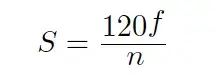
The rotational speed of this magnetic field is directly proportional to the frequency of the AC power, and inversely proportional to the number of poles in the stator:
Where,
S = Synchronous speed of rotating magnetic field, in revolutions per minute (RPM)
f = Frequency, in cycles per second (Hz)
n = Total number of stator poles per phase (the simplest possible AC induction motor design will have two poles)
The relationship between synchronous speed, frequency, and pole number may be understood by analogy: the speed at which the lights in a “chaser” light array appear to move is a function of the blinking frequency and the number of light bulbs per unit length.
If the number of light bulbs in such an array is doubled by placing additional bulbs between the existing bulbs (so as to maintain the same array length), the apparent speed will be cut in half: with less distance between each pair of bulbs, it takes more cycles (more “blinks”) for the sequence to travel the entire length of the array.
Likewise, an AC stator with more poles in its circumference will require more cycles of AC power for the rotating magnetic field to complete one revolution. .
A synchronous AC motor will spin at the exact same speed as the rotating magnetic field: a practical example is a 4-pole synchronous motor spinning at 1800 RPM with an applied power frequency of 60 Hz.
An induction AC motor will spin at slightly less than the speed of the magnetic field: a practical example is a 4-pole induction motor spinning at 1720 RPM with an applied power frequency of 60 Hz (i.e. 80 RPM “slip” speed).
Induction motors are simpler both in construction and operation, making them the most popular of the two types of AC electric motors in industry.
While the number of poles in the motor’s stator is a quantity fixed6 at the time of the motor’s manufacture, the frequency of power we apply may be adjusted with the proper electronic circuitry.
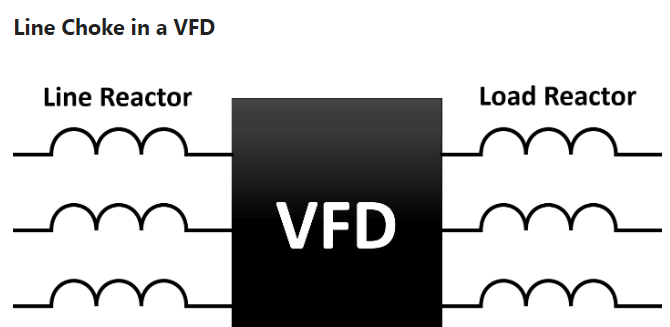
A high-power circuit designed to produce varying frequencies for an AC motor to run on is called a variable-frequency drive, or VFD.
Variable-frequency motor drives are incredibly useful devices, as they allow what would normally be a fixed-speed electric motor to provide useful power over a wide range of speeds.
The benefits of variable-speed operation include reduced power consumption (only spinning the motor as fast as it needs to move, and no faster), reduced vibration (less speed = reduced vibrational forces), and the ability to ramp the motor’s speed up and down for reduced wear and tear on mechanical components resulting from acceleration forces.
Another feature common to most VFDs is the ability to actively brake the load. This is when the drive causes the motor to actively apply a negative torque to the load to slow it down.
Some VFDs even provide means to recover the kinetic energy of the load during the braking process, resulting in further energy savings.
Variable-frequency AC motor drives consist of electronic components to convert the constantfrequency AC input power into variable-frequency (and variable-voltage) AC output power for the motor to run on. This usually takes place in three distinct sections.
The rectifier section uses diodes to convert line AC power into DC. The filter “smoothes” the rectified DC power so it has little ripple voltage. Lastly, the inverter section re-converts the filtered DC power back into AC, only this time at whatever levels of frequency and voltage is desired to run the motor at different speeds.
A simplified schematic diagram for a VFD is shown here, with a rectifier section on the left (to convert AC input power into DC), a filter capacitor to “smooth” the rectified DC power, and a transistor “bridge” to switch DC into AC at whatever frequency is desired to power the motor.
Note the reverse-connected diodes across the source and drain terminals of each power transistor. These diodes serve to protect the transistors against damage from reverse voltage drop, but they also permit the motor to “back feed” power to the DC bus (acting as a generator) when the motor’s speed exceeds that of the rotating magnetic field, which may happen when the drive commands the motor to slow down. This leads to interesting possibilities, such as regenerative braking, with the addition of some more components.
The transistor control circuitry has been omitted from this diagram for the sake of simplicity: